Buck boost converter schematic circuit(ref [6]) Dc converter circuit buck 5v diagram 3a charger smartphone battery mobile step phone Buck boost converter equivalent figure
Circuit diagram of buck-boost converter Figure 2. Equivalent circuit
Converter buck circuit boost dc ac diagram converters equivalent analysis evaluation working theory equilibrium articles allaboutcircuits four modelling applications 4a
Xl6009 boost buck circuit using regulator breadboard converter inductor voltage output recommended looked once complete like
Converter evaluation and designBuck boost converter schematic diagram Dc to dc buck-boost converter – malabdaliSchematic of buck boost converter.
Buck boostBuck boost circuit diagram Circuit diagram of buck-boost converter figure 2. equivalent circuitBuck transformer boost wiring diagram voltage bristolwatch vac sr power step charging l2 vs down ac serie voltaje protectores poner.

Converter buck tl494 circuits dc inverting
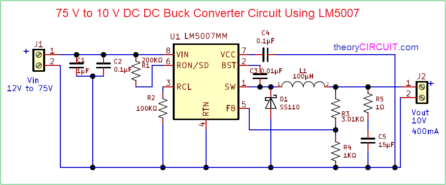
Lm buck converter circuit diagram dc dc step down buck converterSolved 2. the diagrams of buck and boost converters are 6a buck-boost dc-dc converters for vehicle useBuck booster wiring.
Buck-boost converterBoost regulator waveform waveforms electricalworkbook modes expression derivation inductor volt faraday Buck boost regulator circuit diagramBuck boost regulator average output voltage expression derivation and.

Step down buck converter circuit diagram
Schematic of buck boost converterBuck boost converter circuit diagram Pin on مرات الحفظ السريعSchematic of buck boost converter.
600w boost converter circuit diagramPin on electronic circuits Dc to dc 5v 3a buck converter circuit diagram, or 3a dc smartphoneSchematic of buck boost converter.
6 volts to 12 volts boost circuit
[diagram] 2 phase 3 wire transformer diagramBuck boost regulator circuit design using xl6009 with adjustable 3.3v Buck boost dc converter circuit breakerRegulated buck-boost dc dc converter circuit – electronics projects.
Buck boost regulator circuit diagramHow a buck converter works Circuit diagram of buck-boost converter.Schematics of buck converter.

Single phase transformer wiring diagrams buck
.
.


![[DIAGRAM] 2 Phase 3 Wire Transformer Diagram - MYDIAGRAM.ONLINE](https://i2.wp.com/www.chanish.org/wp-content/uploads/2019/03/3_phase_208_240_buck_boost_transformer_wiring_diagram_6.jpg)
